What Did We Observe in an MRO Hotspot Comparison Test?
A thermal image can make an electrical mismatch visible in a way that numbers alone sometimes cannot.
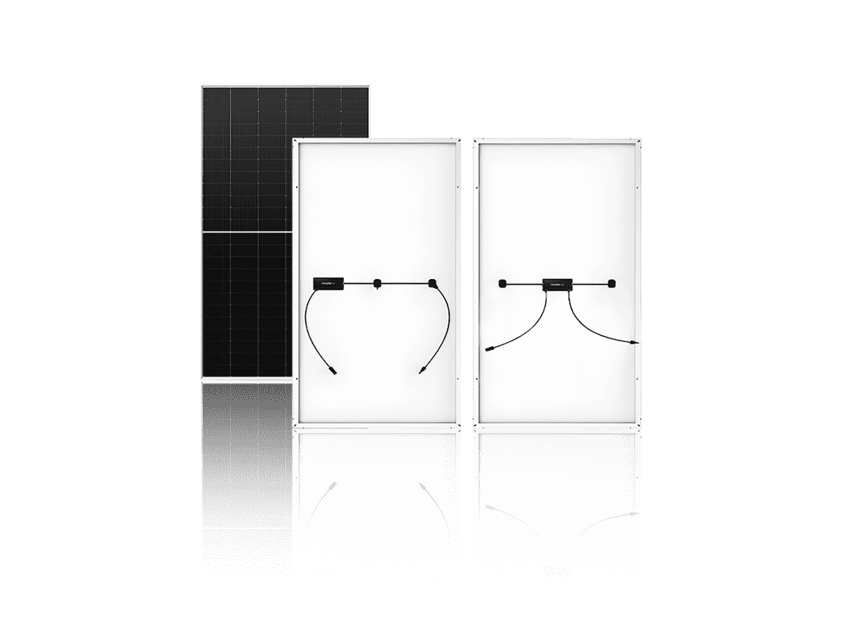
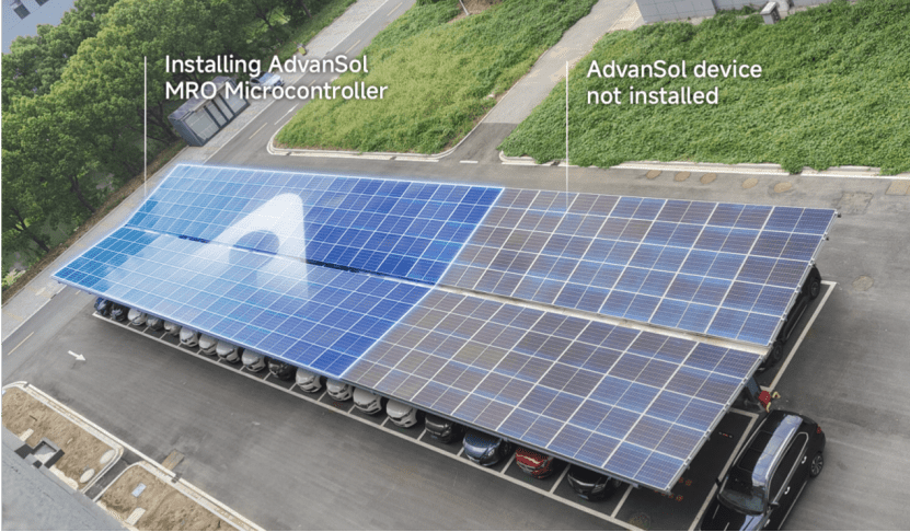
Ina recent AdvanSol internal comparative test, we monitored two PV modules during the same test period—one without an optimizer and one equipped with MRO. Using thermal imaging, we recorded the maximum surface temperature of both modules at 10 corresponding measurement points between 13:36 and 14:32.
What did we observe?
The difference was consistent across the measurement period.
Maximum recorded surface temperature
Without MRO 122.5°C – 157.0°C
With MRO 60.2°C – 73.0°C
At every one of the 10 paired measurement points, the MRO-equipped module recorded a lower maximum surface temperature than the module without MRO
This was not a comparison between the highest reading from one moment and the lowest from another. The two modules were recorded at corresponding times throughout the test period.
Why is this worth looking at?
Under partial shading, a module's I-V characteristics change. Its available power point shifts, and if a bypass diode activates, the module's electrical behavior diverges from the rest of the string.
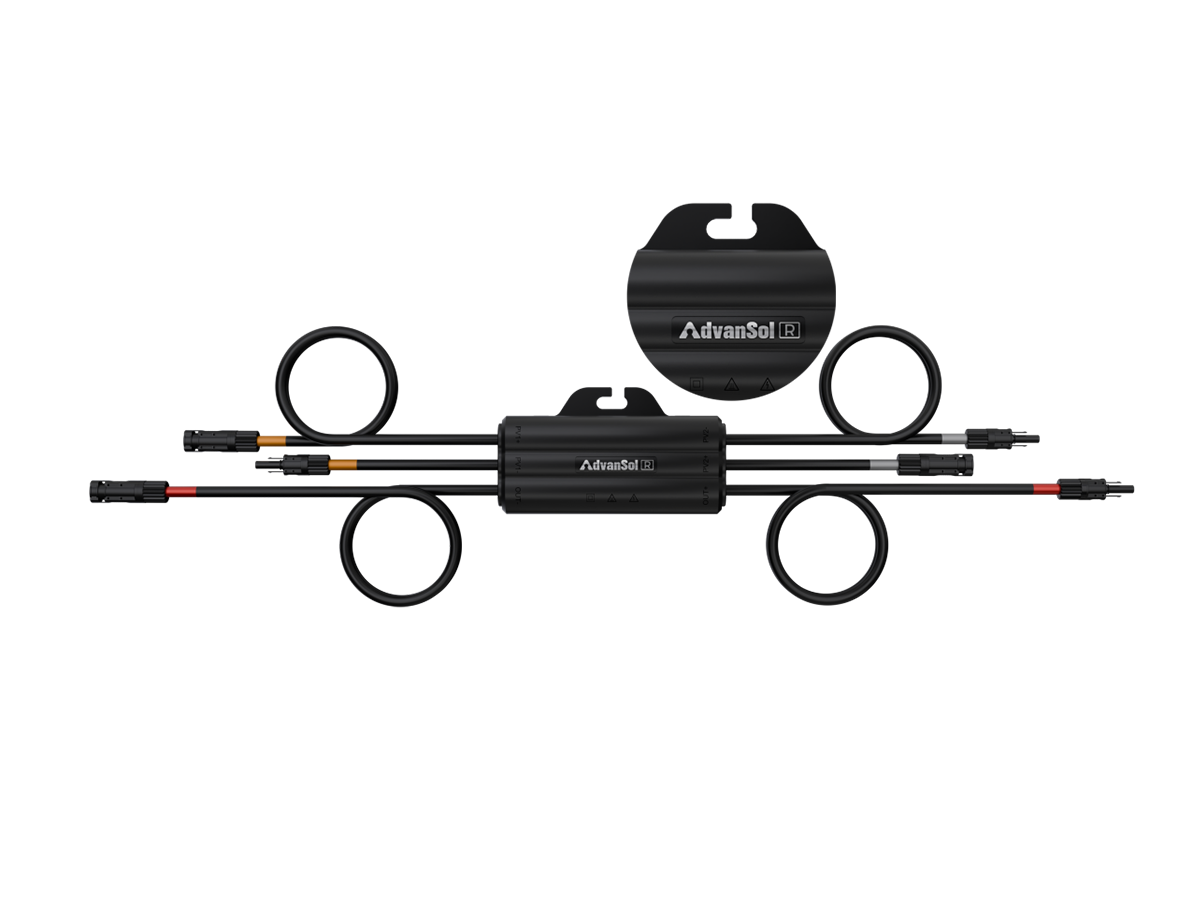
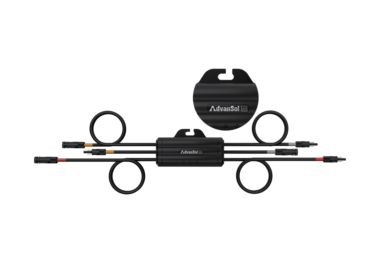
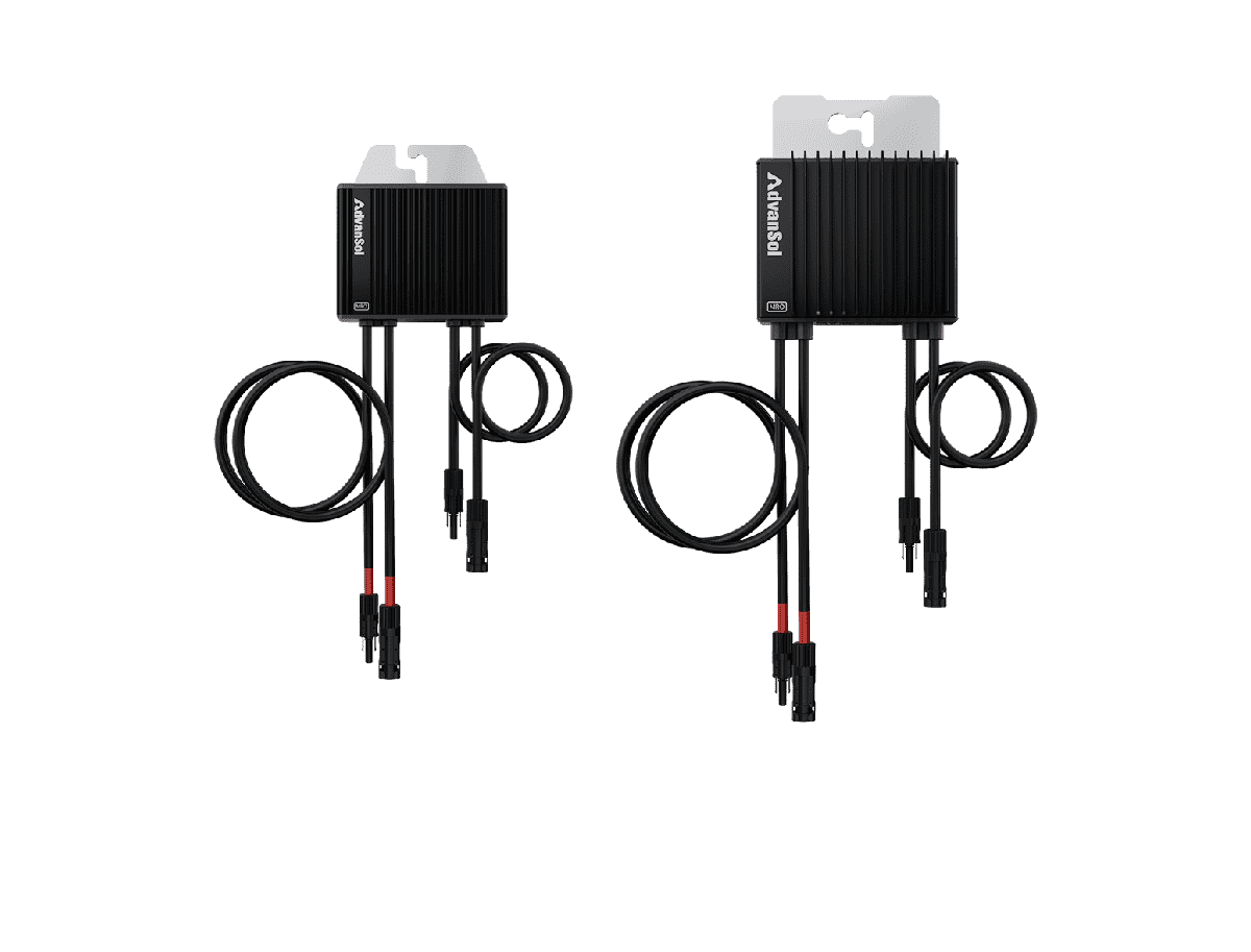
MRO applies MPPT control at the module side, allowing the connected module to operate closer to its own available power point while coordinating with the string. The test provides a visual comparison of thermal behavior alongside a difference in module-side electrical control.
Persistent thermal stress is an important condition to understand when evaluating module behavior under mismatch.
Evidence needs context
It would be easy to take the largest temperature difference from this test and turn it into a headline.
But that would miss the point.
The result of a module-level optimization system depends on the conditions in which it operates—including shading, module characteristics, electrical configuration and the wider system design.
Under this AdvanSol internal comparative test, a clear and consistent difference in maximum surface temperature was observed across all 10 paired measurements between the module with MRO and the module without MRO.
That is an observation we can measure.
Understanding why it happens—and how it translates to different rooftop conditions—requires looking at the electrical system around that observation too.
When mismatch begins at module level, it is worth looking at what is happening at module level—electrically and thermally.
What's the most common mismatch condition you see on complex rooftops—and have you ever used thermal imaging to check how it affects module temperature on site?
AdvanSol internal comparative test. Results are specific to the tested setup and conditions. Actual performance may vary with module type, shading conditions, system configuration and environmental factors.